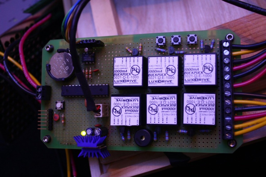
CoraLux LLC was founded in 2013, but the idea for building a better aquarium lighting controller saw its genesis in early 2012 when I prototyped my first aquarium lighting controller. I looked at the field of available “commercial” controllers and wasn’t fully satisfied with what any of them could give me. In particular, I wanted to be able to use all six PWM dimming channels on an ATMEGA328 Arduino chip (whereas the leading solution at the time only allowed 4). Also, I’m a fan of compactness and simplicity. My prototype ended up being bigger than I wanted, but it has worked a treat for over a year. I’ve had more time in 2013 and so I began working on “version 2” of my PWM driver.
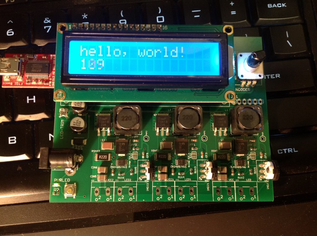
Like I said, I wasn’t satisfied by the size afforded by the through-hole components, and of course the way to solve that is to go with SMD. And so I let ‘er rip on Eagle and came up with the following:
I wouldn’t read too closely into the layout of the board, as it was done as a quick proof-of-concept. It has the major things that I wanted, such as RTC, Arduino ATMEGA328 chip, and single-point input through a pushbutton encoder. The drivers worked out fairly well as well. This version helped me to work out several kinks in the design (yes there were green wire fixes) as well as helping to convince myself that it’d be better to separate the drivers and control board. That way, I could swap out the drivers for whatever was the latest, and also of course in case I burned out a driver channel I wouldn’t have to tear the thing apart and rework the circuit.
Enter version 3.0, where I’ve modularized the control board and drivers separately. On this version I tried to use JST “XH” connectors, which are really nice and give a great positive click upon engagement – but i wasn’t happy with how much space they took up on the board, because ultimately I had plans to create a controller using the PCA9685 16-channel PWM chip and had I used these connectors, there would be no space left! I was also unsatisfied with the layout of the power circuitry. You can see that the barrel connector is on the bottom right of the board, with the power caps and regulator spread about. What I really want is for all of the power circuitry to be concentrated at the point of input, with solid rails bringing the regulated juice to the rest of the board.
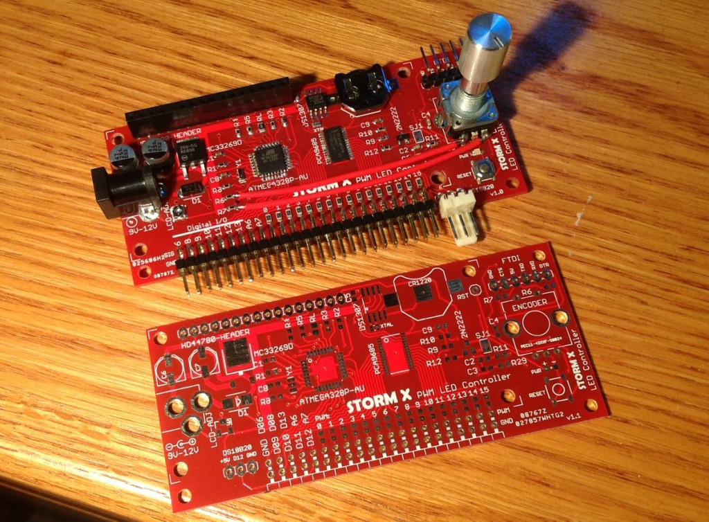
Ok, all of these revs are getting expensive and I’m about out of patience to get to a board layout that I’m satisfied with. With the aforementioned considerations, I jumped on to Version 5. On this version you can clearly see that the power circuitry is contrated in the upper-left corner. I’ve also broken out a digital pin that can be used with a DS18B20 temperature sensor. The plastic encoder has been replaced with a high-quality metal one that has a much better feel to it, and it is long enough to mount a knob above the plane of the LCD for when I get a case on this baby. I’ve gone from CR2032 (20mm) coin cell to CR1220. The downside is a much reduced capacity, although by my estimate it should still allow the RTC to retain time memory for several years (vs over a decade). It’s a trade-off I wanted to take both for aesthetic reasons (the CR2032 looks too big next to the tiny 0603 SMD components) as well as to free up additional board space for something that I planned for further down the road. This, for all intents and purposes is a finalized board.
Version 5 has been working a treat for me for a few months now. I’ve had time to tinker with the code and I believe I’ve come up with an interface that is both intuitive and quick to navigate. The current firmware includes individual channel control for each of the six channels.
This version works pretty well for me, but I was curious what it would be like to have a massive number of channels with higher dimming resolution. Enter the PCA9685 LED Driver chip, most notably used in Adafruit’s breakout board. I decided to bring this chip on-board to create the ultimate single-board solution for PWM LED dimming. At the same time, I addressed some control issues that had to do with encoder button bounce (a low-pass RC circuit as suggsted in the bourns datasheet for the encoder). Using the PCA9685 frees up a bunch of digital pins (basically all six pins that were originally used for 8-bit PWM, arduino pins 3/5/6/9/10/11, are now free to do my bidding). This means that Version X gets to use the true ATMEGA328 interrupt pins 2/3 for really satisfying user-input response. I’ve also commandeered a PWM pin to add a dimming feature to the input LCD via a 2N2222 transistor. Instead of being bright all the time, it will go into standby mode if no user input is detected. The unused pins are all broken out and can be used to drive moonlights, etc, as the user desires. The PCA9685 chip gives tremendous granularity of control with its 4096 dimming levels – so much so that I found that I was able to use Cree Royal Blues as moonlights. Each of the PCA9685 outputs is current protected via a series resistor, so the pins on the board can be used to directly drive most LEDs and drivers.
Something like this could be used for individual channel control for 3 DreamChips, or just a massively built-out LED system.
If you’ve read this far it’s probably obvious to you that I’m geeky, and that I love to build things. I’ve been a builder and maker all my life, and I hope that what I’ve done here can bring some value to your enjoyment of your aquarium.


